8 Tips to Master Reference Planes in Revit Families
Apr 18, 2024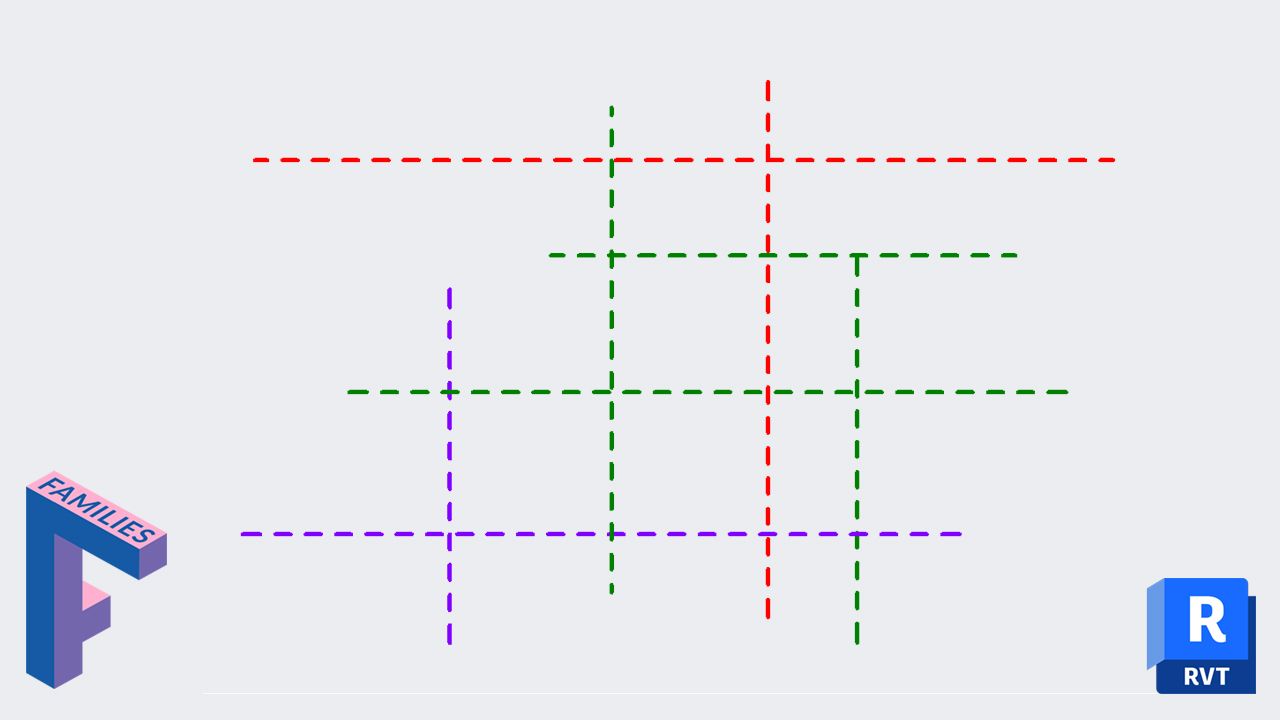
This post is an excerpt from our new HEROIC FAMILIES course for Revit. Learn more and become a Revit Family Mega-Master.

Reference planes are used as tools to define and control the placements of elements and the organization of project and family structures. Reference planes are:

This post focuses on the use of reference planes inside of Revit families. In families, reference planes form the skeleton. They act as bones that can move around to accommodate the skin (geometry).
When adding new reference planes, setting up the IsReference parameter is crucial. When opening the dropdown menu, you will see all these options:

Not a reference: The reference plane can be used to constraint geometry, but it cannot be used as a reference once loaded in the project.
Strong/weak reference: The reference planes will appear as “references” once the family is loaded in the project. That means that the reference plane can be used for dimensions and alignment.
Strong has priority over weak for dimensioning.
Left / Right / Center / etc...: Used to represent specific sides of a family. They act the same way as strong reference planes. Properly setting these up helps when a family is replaced by another.
Weak and strong references aren’t that different. The differences can be subtle and vary from a family category to another.
But let’s give an example. This is a furniture family. In the first one, we used weak references on all sides of the family. In the second, we used strong references.
Let’s align the families to a wall. With weak planes, the entire family is moved, because the geometry has priority over the reference plane. With strong planes, the family stretches to match the wall.

This behavior is inconsistent, though. If we switch the family category to Generic Model, it doesn’t behave that way.
In addition to the IsReference parameter, make sure to enter a name to the reference plane. If it is a major side of the family (front, back, right, left, etc) you can use the same name as the IsReference parameter.

If it is not a name side like left or right, try to give a descriptive name.

To be clear, not setting up a name isn’t the end of the world. It will not break your family. But it will make it much easier for the end-user to use and modify.
Unless you have used the “Not a Reference” option for IsReference, you can put dimensions, snap, and align the family using this reference.
Once inside the Revit project, the IsReference value and reference plane name will be displayed when you hover your cursor over it. Accurate naming is helpful.

If you switch the same reference plane to Not a reference, it cannot be used as a reference in the project anymore.
To set the origin of a family, check the Defines Origin box. Set the origin to two reference planes: vertical and horizontal.

For example, this family origin is located at the center of the family (as indicated by the 0,0 text).

When the dimensions are changed, it will be relative to the center. You can see what happens when you switch types:
In this example, the origin is set to the back and to the left. When the type is changed, the origin doesn’t move relatively to the project.

Plan the origin position: Decide the origin position when you start building a family. For example, a family that will be placed on a wall (such as casework) should probably have its origin on the back side. This way, it won’t intersect with the wall if the dimension changes.
Some families can have dozens of reference planes! It can get confusing to navigate and understand the family. A possible way to make things more clear is to add different colors to the reference plane.
When you create or select a ref. plane, click on Create New Subcategory in the ribbon. Set a descriptive name. Then, select a different color and make sure the line pattern is set to Aligning Line.


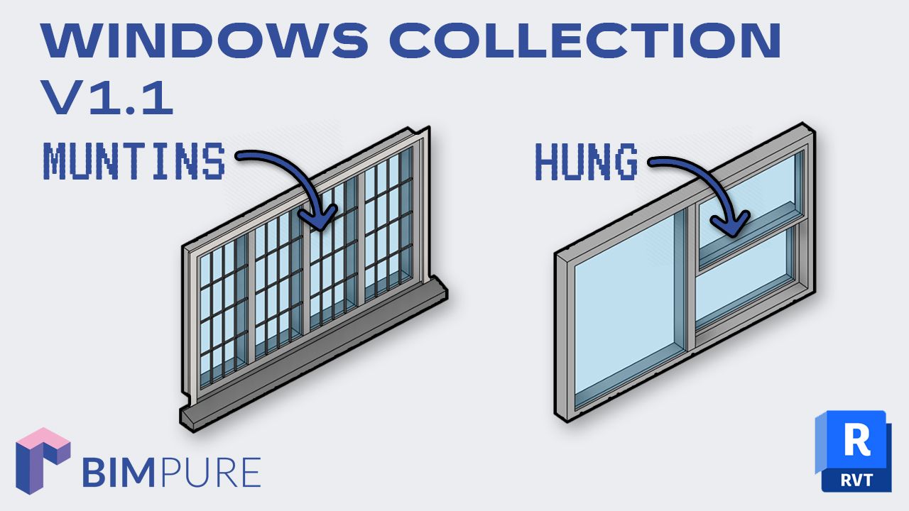
Don’t go too crazy with the different colors. 1, 2, or 3 colors are enough. There are a few ways to use the colored planes. You can indicate the origin of the family. Or you can place them on rough dimensions for door and window families.

In addition to bringing more clarity to your families, naming reference planes can make them helpful for modeling.
In this example, we’ve just created a new reference plane. Let’s give it a name. We call it Pamphlets.

Now, let’s model a new extrusion. Before you start modeling, set a new work plane. In the dropdown menu, you can pick among reference planes that have been named. Reference planes without a name cannot be selected here.

Then, draw the shape of your extrusion. After it’s finished, you can see that the extrusion origin is on the Pamphlets reference plane. 
If you select the extrusion, the “Extrusion End” and “Extrusion Start” values are relative to that Pamphlets reference plane.

Using named reference planes is available not only for extrusion,but also for sweeps, revolve, and other modeling tools.
In addition, it is also possible to place nested face-based or work plane-based families on a named reference plane.
Important note: it is possible to model geometry on an unnamed reference plane. But you’ll have to use the Pick a Plane tool instead of selecting it from the dropdown list.

Reference planes have a “front face” and a “back face”. This affects on the orientation of geometry assigned to the plane.
To know the “front” and the “back” of a reference plane, you need to look at the position of the reference plane name.
The location of the name text is on the back side. In this example, the back side of the reference plane is above:

Why is this important? When creating geometry such as an extrusion, it will go towards the front side by default:

Want more? We've got two more tips about ref planes for you, including how to create extrusions with a negative length value. Download our free pamphlet PDF guides about reference planes in Revit families in the link below.

⏰ Last Chance: Spring Sale ends on April 23rd
🔥 Save big: Get 20% off on all BIM Pure courses & content.
🧠 Get Revit Mastery: Access our full catalog of courses, templates, families, and live events.
Enter your details below to get this free guide.