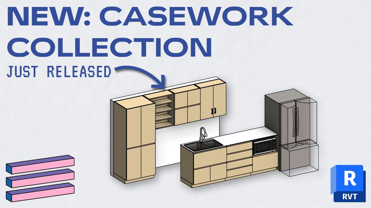
16 Steps to Create a Door Family in Revit
Jul 06, 2019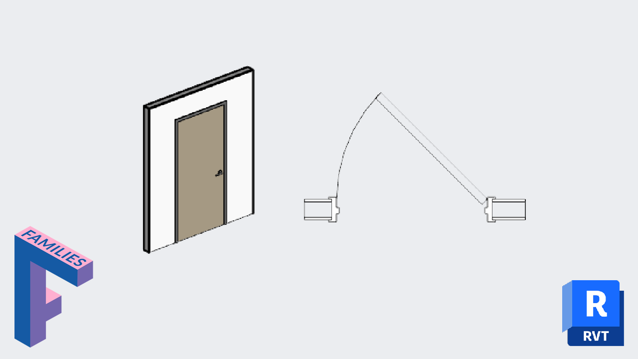
In the previous blog post, we’ve covered all the basic principles to properly create a door family. In this tutorial, we will use this knowledge to create a simple swing door. The door will have a steel frame and will be adapted mostly for an interior use on drywall. It will have a simple panel with no glazing.
It will include a simple handle lever hardware on both side of the panel, with a customizable strike distance height. The door swing will be customizable with an angle parameter. It will include a formula to calculate a value for Rough Height and Rough Width dimensions. The materials will be customizable inside a project for the door frame, door panel and all the hardware.
Some elements will be included directly inside the family, but some other elements will be inserted as nested families.

Create a new family. Use the Metric - Door or Imperial - Door default Autodesk template.

This door family template is made for a residential wooden door family by default. Since we are building a door with a steel frame, you’ll need to delete a few elements. Go to the plan view. Delete the trim elements.

Let’s create additional reference planes to adapt for the full door opening that includes the frame. Go to the front elevation view. Create new reference planes like displayed in red in the image below. Don’t worry about dimensions for now.

The red reference planes are used for more clarity in the tutorial, but it’s ok if you use the standard green ones.
To fully automate the complete door opening, you need to create a new Frame Thickness parameter. Go to the Family Type menu. Click on the small icon to create a new parameter. Use the settings as in the image below.

Type in a standard value for the Frame Thickness, like 50mm. Now, type in formulas like in the image below for both the Rough Width and the Rough Height parameter. These values are calculated by adding the frame thickness to the door height and width. Subtract a number to account for the overlap between the frame and the wall. In this case, we use 19mm.

Now, go back to the family elevation. Add a new dimension between the two red vertical reference planes and the central one. Click on the EQ button.

Create new dimensions as illustrated below. Assign the “Rough Width” and “Rough Height” labels.

In the elevation, select the Opening Cut. Click on Edit Sketch. Use the Align tool (shortcut: AL) to align each boundary line to the red reference planes. Click on the Lock icon to lock the constraint. The opening cut will now include part of the frame instead of just the door panel.

Stay in the elevation view and select the Extrusion tool. Use the Pick Line tool and click on the green reference lines assigned to the Height and Width. Lock all the boundary lines. Then, use the Trim tool (shortcut: TR) to cut the excess line segments. Click on the green check to complete.


Go back to the plan view. Create a new reference plane below the exterior wall face, as in the image below. Create a dimension between the reference planes and assign the “Thickness” parameter to it. Make sure to lock the thickness parameter. Use the Align tool (shortcut: AL) to match the panel to that new reference plane. Click on the lock icon.

The 3D door panel we’ve just created should be visible in 3D views and elevations, but not in a plan view. Instead, we’re going to load a plan swing family later on.
Select the door panel. In the instance parameter, click on Visibility / Graphics Overrides.

Go to the elevation view. Select the Sweep tool. Click on Pick Path, then select the 3 edges of the opening cut. Click the green check to complete.

Draw the sweep profile in the floor plan view. Draw the boundary lines as in the image below. Make sure to lock all the dimensions. Create a new vertical reference plane with the “Frame Thickness” parameter assigned. Keep a 5mm distance from the door panel to the frame middle section. If you want, you can include the frame thickness (like on the right image). Test the frame by changing the door width and the default wall thickness.

When working in view using the Coarse setting, you might want to see a simple frame instead of the complex sweep we’ve created. Select the frame sweep and click on Visibility/Graphics Settings in the instance properties. Uncheck visibility for coarse setting. Then, use the Masking Region tool with Frame/Mullion [cut] lines and create a rectangle that is locked to the reference planes. Make it visible only in coarse views.

Earlier, we deactivated the door panel visibility in plan view. Now, it’s time to load a nested Plan Swing Family. You can use an Autodesk made family, but it would be smart to create your own plan swing family. Be warned: making such a family is not an easy task. We describe all the steps on the Revit Pure Pamphlet you can download at the bottom of this post.
When the family is ready, make sure to associate the Thickness, Width and Swing Angle parameters to the main door family. Align and lock the swing family to the reference planes in the main family.


Now, we’ll insert an Autodesk Handle Lever Family. Go to the Insert tab and click on Load Family. Go to the Hardware subfolder in the doors category. Place the family in a plan view. Align and lock to reference planes. Set and lock distance from the door panel edge.


Go to the elevation view. Create a new horizontal reference plane. Create a dimension from the base level. Assign a new parameter called Strike Distance. See tip 4 if you don’t remember how to create a new length parameter. Align the center of the handles to this reference plane and lock.

Go back to plan view and disable the plan view visibility for the handles.

To properly control the visibility and graphics of each door component, you need to properly assign the correct subcategories. Go to the plan view. Select the door frame sweep. In the instance properties, set it to Frame/Mullion. Repeat the same steps to place the door panel in the Panel subcategory. Make sure to place any door element to the correct subcategory.

You need to create new material parameters for the door frame, panel and all the hardware components.
Click on the door panel. In the instance properties, click on the small rectangle. Create a new parameter called Panel Material. You’ll be able to assign a material once inside a project. Repeat the same step for the frame and create a Frame Material.


Do you want to get this blog post in PDF format? With even more bonus content? Check out our latest pamphlet publication about door families. You will even learn how to create a door swing family.
Enter your details below to get this free guide.