13 Tips to Understand Revit Base Points and Coordinate System
Aug 28, 2025
August 2025 Update: This guide has been fully updated to reflect the latest version of Revit.
Revit's coordinate system can be confusing. This guide explains everything you need to know to get started and avoid rookie mistakes.
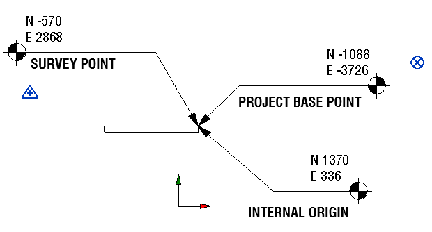
There are 3 different origin points in a Revit project: the Internal Origin, the Project Base Point, and the Survey Point.
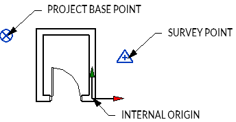
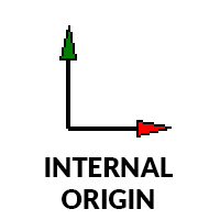
INTERNAL ORIGIN: This is the most important origin point. It represents the building's origin and cannot be moved. You will use this point as the default origin when linking or exporting files.
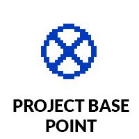
PROJECT BASE POINT: This point is used almost exclusively for internal purpose. It is used to place dimensions relatively to the building. It is represented by a blue circle with a cross in the middle. It can also be used to set the angle difference between the True North and the Project North.
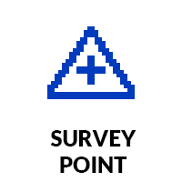
SURVEY POINT: This point is used as the origin for site coordinates. It is typically placed on a site element such as a geodetic marker or property line intersection. In some projects, it can be used as the origin for the shared coordinates and to represent the geolocation data.
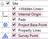
It is crucial to know the position of these points. Go to the Visibility/Graphics menu with shortcut VG. Under the site tool, activate the visibility of all points. They’ll be visible in the view, but won’t print.
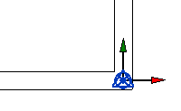
When starting a project or inside a project, it's likely the point will all be together in the same location:
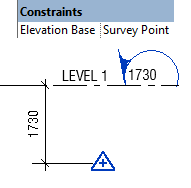
In addition to having an X/Y position, coordinate points have an elevation value.
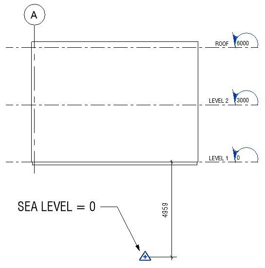
The Internal Origin typically matches level 1.
The Survey Point typically represents the sea level = 0.
The Project Base Point is also typically set to match Level 1. If you want the Level 1 value to be equal to 100’ or 10,000 mm, you can move the Project Base Point vertically. The levels refer to its position.
You need to be extremely careful with coordinate points. Don’t move them unless you’ve got permission from your BIM manager. And if you are the BIM manager, well, you should still think twice before moving them.
The best way to protect their position is to keep them pinned. Select each point and use shortcut PN.
In most cases, the three points share the same position at an intersection of the building.
The Project Base Point can be kept at the same position as the internal origin.
The Survey Point should only be moved when you are ready to integrate shared coordinates.
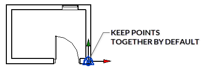
While the default stance is to keep these points together, the next tips will teach you in which cases they should be moved.
Some organizations like the Level 1 to be at height = 0.
Others prefer the height to be at 10,000mm or 100'-0".
Finally, some companies prefer to use the sea level elevation for the level height.
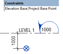
If you want the Level 1 height to start at 0, 100'-0", or 10,000mm, set the Elevation Base value of the level type to Project Base Point. All levels' height values will refer to that point.
If you prefer to position the level height in relation to the sea elevation, you need to set the Elevation Base of the levels to Survey Point.
Regardless of your option, the Internal Origin should match Level 1.
Each project contains a Project North and a True North. Project North is used for modeling and documentation, keeping the building as orthogonal to sheets as possible. True North reflects the real-world orientation. To set the True North angle, select the Project Base Point and input the rotation value.

In each view’s properties, you can choose the orientation. Most views use Project North, while the site plan typically uses True North.

The Spot Coordinate tool is used to specify coordinates relative to one of the three origins. It is located in the Annotate tab.

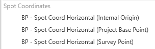
In your template, it’s smart to create a Spot Coordinate type for each of the three origin types.
Start by editing the Spot Coordinate type and use the Duplicate tool to create new versions. Then, scroll down in the Type Properties until you find the Coordinate Origin parameter. Create separate types for each origin point. Relative refers to the Internal Origin of the project.

Once you are done, you should have 3 different Spot Coordinate types.
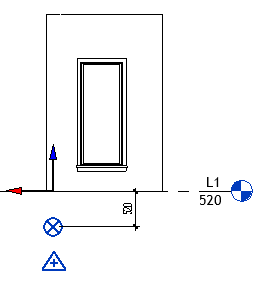
In the example below, each spot coordinate is used to spot the same element. However, they indicate different data since they each refer to a different origin. These tags can be useful when you are confused about the origin's location or want to position an element in relation to one of the points.
When exporting a Revit view to CAD, go to the export settings.
In the Units & Coordinates tab, you can set up the Coordinate system basis for the export.
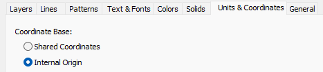
When using the Internal Origin option, this point will match the 0,0,0 point location in AutoCAD.
The other option is called Shared Coordinates. This will use the Survey Point as the 0,0,0 point in AutoCAD.
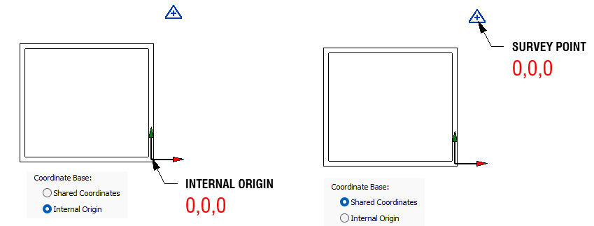
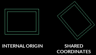
Watch out: If you use the Shared Coordinates setting and enter an angle value for the True North, the project will appear rotated in AutoCAD.
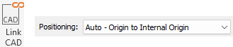
In almost all cases, you should use the Origin to Internal Origin positioning option when linking a CAD file inside your Revit model. The origin of the linked CAD file 0,0,0 will be placed to match Revit's internal origin.
Using the Auto - Shared Coordinates positioning option will match the CAD origin to your Survey Point. That's probably not what you want, unless you are linking a site CAD file and your Survey Point has already been accurately positioned.
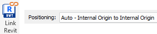
The best option to link Revit files together is to use the Internal Origin to Internal Origin positioning.
When linking a model, it is wise to PIN it immediately. If it moves around by mistake, right-click the model and use the "Reposition to Internal Origin" tool.

The Shared Coordinates linking option isn't necessary... except when you've already set the whole shared coordinate system to all files.
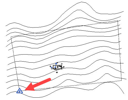
There are two techniques to set the site coordinates, depending on your available data.
Technique 1: Manually move the Survey Point to an appropriate position on the site, such as a geodetic marker or property lines intersection. 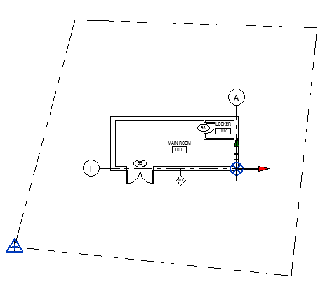
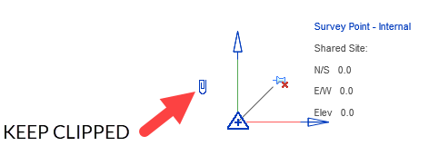
Make sure the Survey Point is clipped when moving it in this strategy.
Also, adjust the height elevation of the Survey Point, as it is set to sea level = 0.
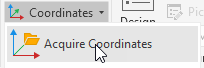
Technique 2: Acquire the coordinates from a CAD or Civil3D file. This assumes you've received good information from your civil engineer or surveyor.
Use the Acquire Coordinates tool in the Manage tab and click the link.
The Survey Point might be automatically moved to match the origin of the CAD file.
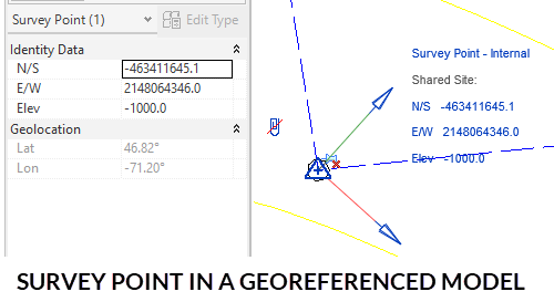
However, it's possible you don't have geolocation information. That's not a big deal; you can use shared coordinates anyway.
If you use this technique to set up the shared coordinates, you should probably unclip the Survey Point before moving it. Otherwise, the entire site will move along with the point.

Oh, there is a secret third option. You can use Forma to import site context into Revit, and your model will be automatically geo-located. Watch our tutorial about it here.
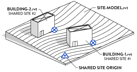
Many users confuse geolocation with shared coordinates. It isn't the same thing.
A Revit model can use shared coordinates without being geolocated. It simply means the Survey Point is used as a common site origin for multiple Revit models.
Think of geolocation as a bonus if you want your site coordinates to refer to a specific point on Earth.
So... how do you geolocate your Revit files?
The first way is to receive a geolocated CAD or Civil3D file from a trusted source. After you acquire the coordinates from these linked files, the longitude and Latitude values are shown in the Survey Point instance properties.
The second method is using Forma, as mentioned in this tutorial.
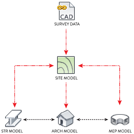
We've just flirted with how to set up the shared coordinates system, but this is a huge topic. It's possible to set up multiple Revit models on the same shared coordinate systems.
You should create a separate site file to set up the shared coordinates, and spread them to all your files, as indicated in this diagram:
But that's a whole ball game.
Want to learn more? Read our guide about Revit shared sites.
Enter your details below to get this free guide.